
Placement clarity
Plans, sections, marks, callouts and schedules that describe the reinforcement arrangement in the correct construction context.
Coordinated reinforcement placement drawings, bar bending schedules, and model-based detailing support for concrete construction teams.
Turn structural reinforcement requirements into clear documentation that connects design drawings, fabrication information, and site placement—with defined review and approval responsibilities.
Global Detailing Consultant supports the production and coordination of rebar detailing documentation for engineers, concrete contractors, reinforcement fabricators, and construction delivery teams. The scope is defined by the project design package, drawing conventions, and client review procedures.
Reinforcing steel is defined by more than a bar diameter and its nominal location. For a construction team to interpret a reinforcement package, drawings must communicate each bar's mark, shape, size, spacing, placement limits, laps, anchorage, cover requirements, and the relationship between adjoining concrete elements. Those details originate from the responsible structural engineer's design information and project specifications. Detailing converts that intent into organized placement and fabrication documentation without silently changing structural design decisions.
For owners, general contractors, concrete subcontractors, and reinforcement fabricators, the value of a coordinated package is practical. Clear drawings reduce ambiguity at handoffs, reveal requests for information earlier, and support consistent communication between modeling, bar scheduling, fabrication, delivery, and site placement. A detailing drawing is not a replacement for the approved structural design; it is a controlled interpretation of that design for the agreed scope.
The appropriate level of detail depends on the concrete system and how the construction team intends to procure and place reinforcement. We can organize detailing support around reinforced concrete foundations, footing mats, grade beams, pedestals, retaining walls, slabs, beams, columns, and structural walls. Each element has different intersections, congestion risks, and sequencing questions, so they should not be handled as interchangeable drawing types.
Foundation packages typically need well-defined top and bottom mats, starter bars, development lengths, and interfaces with walls or columns. Beams and columns require clear stirrup or tie zones, main-bar identification, and continuity at joints. Slab drawings need opening treatments, additional reinforcement around supports, edge conditions, and consistency between plans and bar schedules. For precast concrete detailing, embedded items, lifting information, and component-to-component interfaces may create additional coordination requirements defined by the responsible designer and precast supplier.
A practical reinforcement drawing set combines placement views with an interpretable bar list. Placement drawings organize plan views, elevations, sections, callouts, typical details, references, and notes so the installer can locate each reinforcing arrangement within the correct structural element. Bar bending schedules summarize agreed bar marks, lengths, configurations, grades, counts, and relevant fabrication information, subject to the project's scheduling convention.
The bar schedule should reconcile with the latest drawing revision. A correctly formatted schedule can still be wrong if a bar mark was copied from an older drawing, a hook definition is ambiguous, or a dimensional change was not passed into the takeoff. For that reason, revision comparison and consistency checks are part of preparation, not optional clerical work. Estimation and quantity takeoffs should clearly distinguish scheduled quantities from contingency, waste allowance, or procurement assumptions specified by the client.
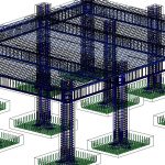
Three-dimensional reinforcement models can help teams interpret crowded intersections that are hard to read from disconnected plan and section views. Model-based coordination may be useful around column-beam joints, transfer elements, openings, embed plates, congested foundations, and interfaces between cast-in-place and precast concrete. A model also supports visual review of bar location relative to the concrete envelope and coordinated reference geometry.
A 3D model does not itself prove constructability or structural adequacy. Bar bend radii, permissible fabrication shapes, clearances, design tolerances, and site access require review against the governing project requirements. Where existing models or drawings conflict, the discrepancy should be recorded and referred to the responsible team instead of resolved through unapproved assumptions. Related building information modeling support can improve reference coordination when model status, ownership, and exchange formats are defined at project commencement.
A reliable kickoff starts with structural plans, approved reinforcement schedules or notes where available, current specifications, relevant architectural and civil backgrounds, grid and level references, revision logs, and identified project contacts. If partial sketches, old paper records, or scan-only drawings are the starting point, the document status must be made clear. Our paper-to-CAD drafting service can support conversion of source documents into editable backgrounds, but incomplete dimensions or unreadable notes require confirmation rather than inferred engineering values.
Depending on the agreed scope, deliverables may comprise reinforcement placement drawings, element-specific sections, 2D or 3D reference views, bar bending schedules, quantity summaries, drawing indexes, revision logs, and response-to-comment registers. The required native or exchange file formats, layers, title blocks, naming rules, and submission stages should be established before production begins. All outputs should be reviewed against the supplied design basis and assigned responsibility boundaries.
At intake, the team checks drawing completeness, identifies governing versions, and creates a register of source documents and open questions. During the clarification stage, conflicting marks, omitted dimensions, uncertain construction joints, or unclear lap instructions are returned to the client's engineering contact. The detailing stage then develops element views, scheduling data, and supporting references together so they can be reconciled during checking.
Quality review should compare current drawings with the approved source, evaluate placement consistency across views, inspect bar marks and schedule totals, and verify that comments were incorporated into the intended revision. A controlled issue package is assembled with revision identifiers and a clear list of outstanding matters. Later design changes enter the same process: assess the affected elements, amend drawings and schedules, and record which issue supersedes the previous set. This is particularly important when fabrication and field installation occur in different locations.
Rebar detailing sits between structural design information and construction documentation. It can expose practical questions about bar congestion, embed conflicts, concrete cover representation, and sequencing, but decisions that change the structural design, connection behavior, or specified reinforcement must be approved by the designated responsible professional. Detailing support should not be described as independently certifying code compliance or issuing licensed engineering approvals.
Review roles should be established at project kickoff. The responsible engineer defines and approves design criteria; the detailing team documents the instructions and raises discrepancies; fabricators and installers confirm their production and placement constraints; and the client determines final approval and issue status. Where project-specific standards or international conventions apply, the relevant editions, units, notation, bending conventions, and required submittal format should be supplied and confirmed rather than assumed.
Rebar detailing is used across commercial, residential, institutional, infrastructure, and industrial concrete construction. The documentation scope differs across foundations, building frames, retaining structures, equipment pads, utility works, and precast components. For international clients, it is important to confirm whether dimensions use metric or imperial units, how bar sizes are designated, and which notation system the receiving fabricator follows.
Cross-border work also depends on disciplined communication. We recommend a shared question register, a designated approval contact, predictable review milestones, and explicit cutoffs for incorporating design changes. Structural and miscellaneous steel packages can be coordinated with related steel detailing services when steel-to-concrete interfaces need consistent reference dimensions. Examples of visual documentation types can be reviewed on the engineering work samples page, without assuming that a sample represents the scope or approval status of a new assignment.
Plans, sections, marks, callouts and schedules that describe the reinforcement arrangement in the correct construction context.
Documented drawing status and checks that connect design comments to the relevant reinforcement details.
Defined responsibilities for technical questions, design approvals, fabrication data and field interpretation.
A typical scope may include reinforcement placement plans, beam and column sections, footing and wall details, bar mark identification, bar bending schedules, and coordinated 2D or 3D views. The actual issue package depends on the structural design information, client specifications, and the agreed fabrication and construction workflow.
Yes, legible paper, scanned, or PDF drawings can be used as a starting point for drafting or reconstruction. However, outdated revisions, unclear dimensions, and missing reinforcement notes must be clarified before they become part of a controlled detailing package. Converting a drawing into CAD does not validate the underlying structural design.
They can support quantities and fabrication planning, but their use for purchasing depends on the schedule convention, source revisions, scope of included elements, allowances, and the client’s procurement rules. A quantity report should identify those assumptions and should not be treated as an independent design or inventory approval.
The engineer or other professional designated by the project remains responsible for design decisions and approvals. Detailers can document existing requirements, flag conflicts, and incorporate formally approved responses. A proposed change to bar arrangement, anchorage, spacing, or structural performance should never be silently treated as a routine drawing edit.
Share your project scope, current drawing status, expected outputs, and review schedule with our team.